Today, we’re discussing the Gradient Array. Well—more accurately—the Gradient Arrays. The Gradient Array actually comes in two flavors, the Edge Gradient and the Strong Gradient. Fun fact, we recommend the Strong Gradient array the most to our customers. Why? Well, read on to find out!
By the way, this is the eighth article in our series exploring some common (and uncommon) electrode arrays.
We’ve also covered the following:
Part 2: The Schlumberger Array
Part 3: The Dipole-Dipole Array
A quick refresher on electrode arrays (in less than 30 words):
Electrode arrays are different arrangements of electrodes used to perform geophysical resistivity measurements. Electrode arrays were developed in order to make field measurements more efficient and data interpretation easier.
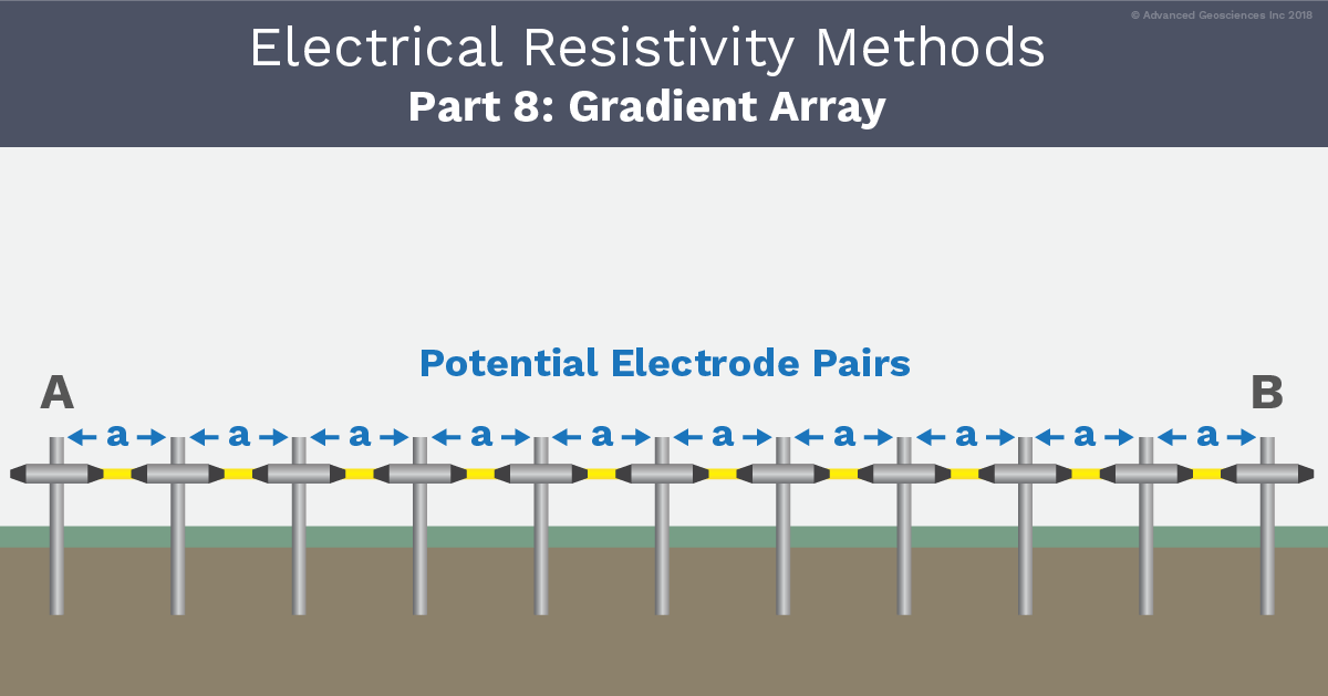
What is the Gradient Array?
Let's start with what the Gradient Array is first before we discuss the 2 different types. The Gradient Array is similar to the Schlumberger array. The difference is that the Schlumberger array records only the center receiver dipole, whereas the gradient array measures all adjacent dipoles from one transmitter electrode to the other, including the center-most dipole.
To take a measurement with the Gradient Array, a reading is taken of the potential field between two current electrodes side-by-side (which form a dipole). The next reading goes one step to the right and continues down the row of electrodes. This process repeats until you’ve mapped the whole area you’re examining. The lateral changes in the potential field of the Gradient Array are measured between the transmitter dipole A&B. Recording the lateral changes is often referred to as a profiling method.
What is the difference between Edge Gradient and Strong Gradient?
As mentioned above, the two forms of Gradient Array that can be used for 2D profiles are the Edge Gradient and the Strong Gradient.
All measurements on an Edge Gradient use the "a" electrode spacing between the transmitters A&B. Current electrodes—starting with the B-current electrode—remain at the first electrode until the A-current electrode reaches the last electrode on the 2D line. Then, the A-current electrode remains at the last electrode until the B-current electrode reaches the A-current electrode. This Gradient Array generates a large number of measurements.

Above: A simulation of the Edge Gradient in AGI EarthImager™. A & B are represented by the red squares.
Alternatively, the measurements on a Strong Gradient is comprised of multiples of eight measurements. These are always taken between two transmitting electrodes with different "a" electrode spacing like a, 2a, 3a, 4a, etc..

Above: A simulation of the Strong Gradient in AGI EarthImager™. A & B are represented by the red squares.
Benefits, Considerations, & Applications Of The Gradient Array
Benefits: A full spread of 56 electrodes with one meter spacing between will give you a very strong signal near the two current electrodes using the Edge Gradient. (but a very weak signal in the center of your survey area). The Strong Gradient Array is a good choice to improve such weak signal issues. Strong Gradient produces a strong signal and it is recommended for a large number of electrodes to reduce the number of measurements. This is one of the reasons we recommend the Strong Gradient for most geophysical surveys—even just as a backup array.
Considerations: Historically, these arrays were considered to be impractical, slow, and hard to visualize. Before automatic multi-electrode systems, resistivity imaging instruments most often consisted of four electrodes connected to a voltmeter. Using the Gradient Array with this type of system was very time consuming, as it requires someone to take readings and then move the electrodes until the whole survey area was mapped. But with modern multi-electrode resistivity imaging systems like the SuperSting™ WiFi, you can automatically take measurements between each dipole for a quick and efficient survey.
Since Gradient Arrays, especially the Edge Gradient Array, frequently depend on the first and last electrodes on the survey line, it is highly recommended to closely observe the contact resistances on these electrodes during the entirety of your survey to reduce noisy data.
Applications: Profiling methods such as the Gradient Array are ideal for locating sinkholes, fractures, and other geological changes. The Strong Gradient Array is also great for conductive environments such as on the seafloor to enhance measured signal.
